This post explains the essential functionality of the DMA block that is present in the Gigabit Ethernet Controller in the Processing System (PS) of ZYNQ devices and also demonstrates a practical application. The goal of the experimental part will be to modify an example application such that the system becomes ready to continuously receive Ethernet frames and loop these frames back to the original sender. The demonstration will be tested in the Digilent ZYBO board, but of course, it can be adapted to any ZYNQ board featuring an Ethernet interface.
This post is complementary to the tutorial about ZYNQ Ethernet that was posted earlier. It explores the same example application, namely the xemacps_example_intr_dma example that can be imported through the Xilinx SDK and the same hardware design (detailed there). Therefore, it is highly recommended that you refer to the other post first.
Before starting, I should note that this post has the purpose of merely facilitating the understanding of the ZYNQ Ethernet DMA block. It is by no means a substitute for the official documentation. The interested reader can find the complete and detailed information in the ZYNQ manual. Besides, I do not guarantee the correctness of the information and encourage you to correct me if anything seems to be wrong.
Background
The Gigabit Ethernet Controller
The Gigabit Ethernet Controller (abbreviated as GEM within Xilinx documentation) that is available in the PS of ZYNQ devices features a DMA block with Scatter-Gather functionality. This block coordinates the movements of data coming and leaving the Ethernet interface into memory. Therefore, any application using the ZYNQ Ethernet must properly configure and drive the DMA block.
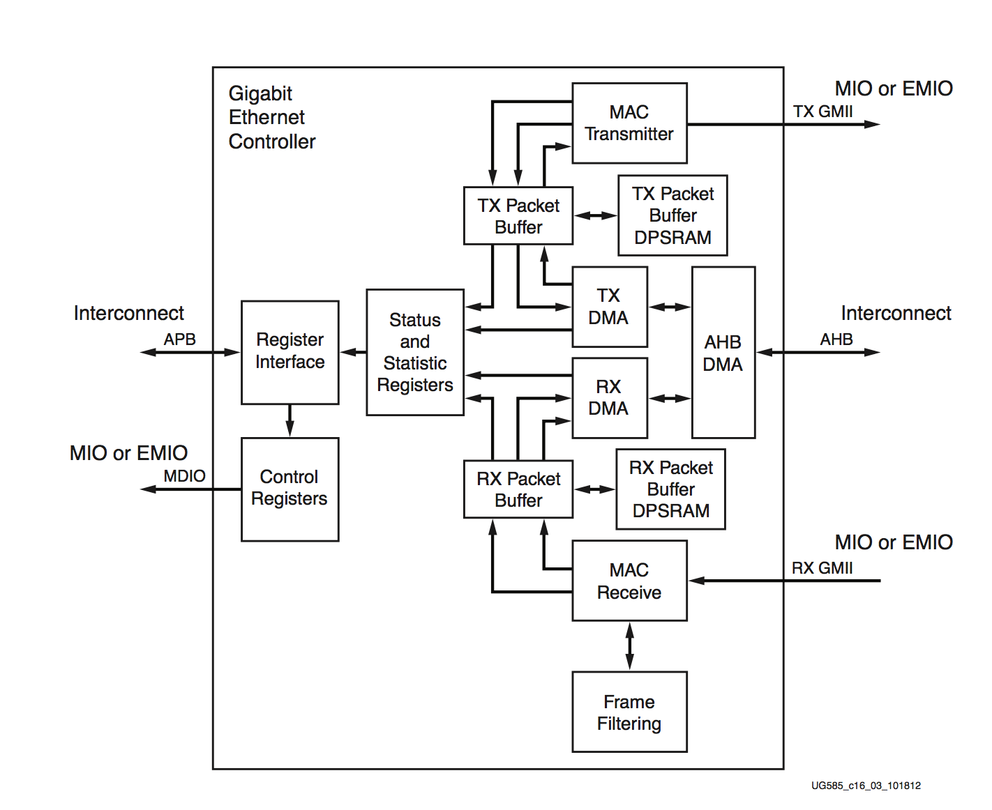
As seen in the Gigabit Ethernet Controller diagram below, data received down at the Ethernet PHY goes up (in the layer stack) to the Ethernet Rx MAC through the “RX GMII” interface. Then, first, the received packet is stored in the RX Packet Buffer, then transferred by the RX DMA towards memory through the AHB interface. In the opposite direction, data to be transmitted is first fetched from memory through the AHB interface and written into the TX Packet Buffer by the TX DMA module. Once an entire frame is ready at the TX Packet Buffer, the MAC starts to transmit it down to the PHY through the TX GMII interface.
Buffers and Buffer Descriptors in the GEM
The DMA-handled data transfers must be orchestrated by the so-called buffer descriptors. In case this concept is new to you, a buffer descriptor (BD) is a data structure containing a pointer to the initial address of a memory region (in this context known as a buffer) and an entry that determines the amount of data to be read/written from/into that region (equivalent to the length of the memory region, or possibly referred as the length of the data transfer). Furthermore, it often has more information about the buffer itself and about the data transfer. For example, one common entry in a BD is a pointer to another BD that should be processed right after the data transfer to or from the pointed address is concluded, often known as the “next pointer.” The latter, by the way, is not present in the BDs that are used in the GEM.
The user application must properly configure these BDs, but once they start to be processed by the hardware, no intervention by the user application is required until the last BD is processed. It is all done in hardware. Ultimately, one or more BDs can be used to complete a particular data transfer. This is essentially what is known as Scatter-Gather DMA mode (the name comes from scattering or gathering distinct memory regions). The other alternative would be for the processor to instruct the DMA block directly whenever a DMA transaction is required, but this requires more frequent intervention of the CPU, so it is generally less efficient. In the specific case of the DMA that is present in the GEM, such a mode of operation is not even an option.
So, just to be clear, there are buffers (memory regions) and buffer descriptors. Buffers are used to store data that is going to be read via DMA or to receive data written through the DMA. In contrast, BDs are used to program DMA read or write transactions. Nonetheless, note both of them are stored in memory. That is, there must be a memory region allocated for all the individual buffers and another memory region to store the BDs.
Queue Pointer Registers
In the specific case of the GEM, in addition to BDs and buffers, there are still the so-called queue pointer registers (one for Tx and another for Rx). These are the registers that point to the enqueued BD that is to be processed next. After the conclusion of the transaction described in the pointed BD, the queue pointer is updated to point to the subsequent BD. Namely, it is incremented by the BD length (two words in this case). Whenever the current BD has a condition that indicates it is the last BD in a list of BDs (by the wrap bit, explained in the sequel), the queue pointer wraps back to the queue base address, that is, to the address of the first BD in the list. The latter, in turn, is maintained in a specific register called the queue base address register (again, one for Tx and another for Rx).
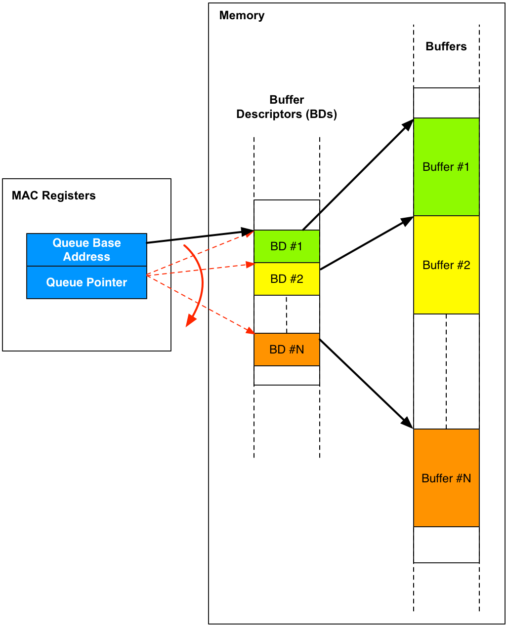
In summary, the components shown in the diagram below are the ones that are present for both Tx and Rx chains in the GEM. Note that BDs point to buffers, that the queue pointer points to the current BD (to be processed next) and that the queue base address always points to the first BD in the list. Furthermore, note BDs and buffers are stored in memory, while the queue base address and queue pointers are registers within the Gigabit Ethernet MAC.
Composition of Buffer Descriptors
Each BD of the GEM DMA is composed of two 32-bit words: one for the buffer address and the other for configuration and status. The status/control words in the BDs for Rx and Tx are different, but one thing that they have in common is that both contain the length of the buffer. The second common entry is a bit called wrap. When the hardware is processing a list of BDs and encounters a BD with this bit set, it wraps (as the name implies) back to the address of the first BD in the list.
Each BD describes a memory region that can contain part of an Ethernet frame or even a full frame (for either transmission or from reception). When a BD points to a partial frame, the BDs that together point to the memory regions composing a full frame are processed sequentially. Since the last BD in the sequence flags the wrap bit, the engine that fetches the BDs can infer that the BD list has been completely processed and trigger an interrupt.
In addition to the wrap bit in the BD, there are other bits that are essential to the DMA operation. The first is the ownership bit preset in Rx BDs. Whenever frame data is written in the buffer pointed by a certain Rx BD, the DMA controller sets this ownership bit to 1. This means the buffer has been used, namely that it is now “owned” by software, so it is not available anymore for the hardware. On the Tx side, a similar role is played by the used bit. The hardware sets this bit to 1 once the buffer data is successfully transmitted, so the bit indicates whether the buffer has been used (transmitted). The software is responsible for clearing this bit before requesting a transmission because the hardware interrupts with an error indication in case transmission of a “used” BD is requested.
Specifically for the RX BDs, there are two other important status indicators: the start-of-frame (SOF) and end-of-frame (EOF) bits. When receiving a frame, the DMA controller uses the number of BDs that is necessary to store the complete frame. Since the Ethernet frame length itself is variable, the number of BDs per frame also varies. The first BD of a given frame is marked with the SOF and the last BD is marked with EOF, so that software can understand how many frames have been received. Besides, note that what really causes the DMA engine to wrap back to the first BD in the BD list (or ring) is the wrap bit, not the EOF. So, depending on the number of buffers available, a BD ring could receive more than one frame.
In the case of TX BDs, there is also the last bit, which is similar to the EOF of RX BDs. The last bit indicates when the BD points to the last buffer pertaining to the current frame being transmitted.
In summary, the following fields in the status/control word are essential to the basic DMA operation:
| TX BDs | RX BDs |
|---|---|
wrap | wrap |
used | ownership |
last | EOF |
SOF | |
| Buffer length | Buffer length |
BD State Machine
BDs can be in four different states at any given moment. As DMA transactions occur, they cycle over these states. This section gives an overview about them.
The following diagram shows the states over which a BD transitions in its lifecycle. First of all, a collection of BDs denominated BD Ring is created using the XEmacPs_BdRingCreate() function of the XEMACPS drivers (specifically at xemacps_bdring.c). This function creates the number of BDs that is passed as argument and leaves them all in the “Free” (or “Idle“) state. This is the state that the BDs are when they are not yet controlled by the user application and not programmed for any DMA transaction.
In order for the application to gain control over the BDs, so that it is possible to program them for a certain DMA transaction, it has to call the XEmacPs_BdRingAlloc() function. By calling this function, the BDs transition into the “Pre-Process” (or “Pre-work“) state and the user application, then, is allowed to configure them, for example by specifying the buffer addresses that the BDs should point, the transfer lengths and so on. In the case of the XEMACPS drivers, this is done by function XEmacPs_BdSetAddressRx() (or the Tx variant).
The final step prior to the actual transaction is to enqueue the descriptors in hardware, which is done by the XEmacPs_BdRingToHw() function. After the latter is called, the BDs transition to the “Hardware” (or “Work“) state, in which they are under hardware control.

After the BD ring is processed, that is, after the corresponding DMA transactions are completed, the BDs remain in hardware until the user application reclaims control of them by calling the XEmacPs_BdRingFromHwTx (or the Rx variant). By doing so, the BDs transition into the “Post-Process” (or “Post-Work”) state, in which the application has access to the BDs and, consequently, is able to check the status of the transactions (by inspecting the status word of each BD). In the end, the application checks the status indicators and infers whether the transactions were successful or not.
Finally, after the BDs are post-processed, they can be freed, so that they can become ready to be used again. With that, the BD ring returns to its initial state and remains there until the next cycle initiates.
Example Application
This section analyzes the code adopted in the Ethernet example application xemacps_example_intr_dma that can be imported through the SDK. As noted at the beginning of the post, before advancing, you should first check the previous post about the ZYNQ Ethernet interface. There, you can find the steps for the design of the hardware that you need here and also an overview about the Ethernet configuration that must be done by the application (run in the ARM host).
DMA Interrupts – Tx, Rx, and Error Callbacks
The DMA engine of the Ethernet controller operates based on interrupts. In particular, an interrupt is asserted whenever a certain DMA transmission or reception is concluded. The interrupt occurs in the Gigabit Ethernet (GigE) controller but is routed to a block in the PS called Generic Interrupt Controller (GIC), as depicted in the PS diagram below. The latter has connections to interrupts signals from all sorts of I/O Peripherals within the PS and could also be connected to PL interrupts.
The GIC is responsible for managing the interrupt priorities before passing them to the CPU. That is, since several interrupts are connected to it, and these can occur at the same time, the module decides which interrupt should be passed to the processor first. Ultimately, the GIC interrupts the processor and indicates the interrupt so that the appropriate interrupt service routine (ISR) can be called.

The GEM DMA, in particular, can raise “send”, “receive” and “error” interrupt conditions. Whenever one of these interrupts occurs, a single interrupt signal (IRQ) is asserted by the GEM, and a single ISR is called by the application. You can see that by observing the following lines within the EmacPsSetupIntrSystem() function:
/*
 * Connect a device driver handler that will be called when an
 * interrupt for the device occurs, the device driver handler performs
 * the specific interrupt processing for the device.
 */
Status = XScuGic_Connect(IntcInstancePtr, EmacPsIntrId,
		(Xil_InterruptHandler) XEmacPs_IntrHandler,
		(void *) EmacPsInstancePtr);
where XEmacPs_IntrHandler is the “master” (single) interrupt handler. Then, if you go into the definition of this ISR, you can see that it infers the specific interrupt condition by reading the GEM registers. Once the condition (transmission, reception, or error) is known, the appropriate callback handler is called: either RecvHandler, SendHandler or ErrorHandler.
These handlers are specifically defined before the interrupt system is initialized. You can check the following lines within EmacPsDmaIntrExample():
/*
 * Setup callbacks
 */
Status = XEmacPs_SetHandler(EmacPsInstancePtr,
			     XEMACPS_HANDLER_DMASEND,
			     (void *) XEmacPsSendHandler,
			     EmacPsInstancePtr);
Status |=
	XEmacPs_SetHandler(EmacPsInstancePtr,
			    XEMACPS_HANDLER_DMARECV,
			    (void *) XEmacPsRecvHandler,
			    EmacPsInstancePtr);
Status |=
	XEmacPs_SetHandler(EmacPsInstancePtr, XEMACPS_HANDLER_ERROR,
			    (void *) XEmacPsErrorHandler,
			    EmacPsInstancePtr);
The callback called after data is transmitted essentially increments a counter of the number of frames that were transmitted (FramesTx). Similarly, the receive callback handler increments the count of received frames (FramesRx). Finally, the error callback increments the number of errors that have occurred and also digests the error code to understand which one has occurred. In the latter case, one example is when an overrun occurs in the buffer that stores Rx Ethernet data.
BD Ring Creation
With respect to BDs, the first step is to create the structures that control the BD rings for Tx and Rx. The XEmacPs struct created by the XEmacPs_CfgInitialize() function by default contains two preallocated (empty) BD Rings, the TxBdRing and RxBdRing. Then, these BDs are defined once XEmacPs_BdRingCreate() is called. For example, for the RX BD Ring, the following code is used to create a ring of RXBD_CNT BDs (in this case 32):
Status = XEmacPs_BdRingCreate(&(XEmacPs_GetRxRing(EmacPsInstancePtr)),
			       (UINTPTR) RX_BD_LIST_START_ADDRESS,
			       (UINTPTR)RX_BD_LIST_START_ADDRESS,
			       XEMACPS_BD_ALIGNMENT,
			       RXBD_CNT);
By doing so, the BD ring is created, and all of its BDs are initialized in the free state of the BD state machine. Besides, if you look at the implementation, you can see that creation of a BD ring executes a memset to set the entire BD ring memory region to 0, as follows:
(void)memset((void *) VirtAddrLoc, 0, (RingPtr->Separation * BdCount));
Namely, after the above command, the BD ring exists in memory, but the BDs have no content yet.
Next, a single empty (cleared) BD named BdTemplate is cloned to all BDs in the ring (note the highlighted lines):
XEmacPs_BdClear(&BdTemplate);

/*
 * Create the RxBD ring
 */
Status = XEmacPs_BdRingCreate(&(XEmacPs_GetRxRing(EmacPsInstancePtr)),
			       (UINTPTR) RX_BD_LIST_START_ADDRESS,
			       (UINTPTR)RX_BD_LIST_START_ADDRESS,
			       XEMACPS_BD_ALIGNMENT,
			       RXBD_CNT);
if (Status != XST_SUCCESS) {
	EmacPsUtilErrorTrap
		("Error setting up RxBD space, BdRingCreate");
	return XST_FAILURE;
}

Status = XEmacPs_BdRingClone(&(XEmacPs_GetRxRing(EmacPsInstancePtr)),
			      &BdTemplate, XEMACPS_RECV);
if (Status != XST_SUCCESS) {
	EmacPsUtilErrorTrap
		("Error setting up RxBD space, BdRingClone");
	return XST_FAILURE;
}
Here, in contrast, a memcpy is executed to copy the template BD to all BDs in the ring. At this point, the BD ring remains entirely in the “free” state, but now its BDs have content (the template BD), and the wrap bit is set for the last BD in the ring. Besides, it is only because the ring is in the “free” state that it is possible to clone the template BD. Otherwise, for example, if the BDs were in the “pre-process” state, such direct modification of BDs would not be allowed.
The same procedure is carried out for the Tx BDs. The only difference is that, before doing so, the used bit is asserted on the BD template that is cloned to all BDs in the Tx ring. The motivation is that, as pointed out earlier, the software must clear the used bit right before transmitting is enabled (see the example in 16.3.8 of the ZYNQ manual). This step is accomplished by the following line:
XEmacPs_BdSetStatus(&BdTemplate, XEMACPS_TXBUF_USED_MASK);
RX BD Ring State Transitions
During transmission, the BDs transition along with their state machine just as described earlier. Namely, first BDs are allocated, then enqueued to hardware. Later on, the BDs are retrieved from hardware and freed.
Within the EmacPsDmaSingleFrameIntrExample() function, you can see the following:
Status = XEmacPs_BdRingAlloc(&(XEmacPs_GetRxRing(EmacPsInstancePtr)),
			      1, &BdRxPtr);
where the arguments imply the request for allocation of a single BD (the second argument). This function, in turn, checks whether there is a sufficient number of “free” BDs in the ring to cover the requested number of BDs and, in the positive case, allocates them so that they transition into the “pre-process” state. The result is returned by the third parameter of the call, &BdRxPtr, which is the address of a pointer. The function internally configures this pointer to the address of the first among the BDs that it allocates. The application needs this pointer to configure the BDs for the desired DMA transaction.
In fact, this is what is done next. The address allocated for the receive (Rx) Frame is written to the first BD word, which points to the memory region where received data should be stored. This is done by the following:
XEmacPs_BdSetAddressRx(BdRxPtr, (UINTPTR)&RxFrame);
After that, the allocated BDs (in this case only 1) are enqueued in hardware by:
/*
 * Enqueue to HW
 */
Status = XEmacPs_BdRingToHw(&(XEmacPs_GetRxRing(EmacPsInstancePtr)),
			    1, BdRxPtr);
At this point, they are already in the “Hardware” state. Hence, as soon as the DMA “turns on” (so far it is off) and data is received through the Ethernet interface, the engine will process the requested DMA transactions.
Subsequently, the GEM’s receive chain is enabled:
/*
 * Start the device
 */
XEmacPs_Start(EmacPsInstancePtr);
Then, once a frame is received, it will trigger an interrupt. The latter, in turn, will increment the count of received frames. This count, in particular, is used in a “busy wait.” More specifically, at a certain point, the application waits for received data by doing the following:
while (!FramesRx);
As soon as the interrupt occurs and FramesRx is incremented, it leaves the while loop.
After leaving the loop, the application reclaims control of the BDs that were previously enqueued in hardware. This is done by the following:
NumRxBuf = XEmacPs_BdRingFromHwRx(&(XEmacPs_GetRxRing
					  (EmacPsInstancePtr)), 1,
					 &BdRxPtr);
The above function searches up to a given number of BDs (in this case 1 – the second argument) that are in the Hardware state and verifies the used bit for each of them. As soon as it finds a BD that has not been used yet, it stops and returns the number of BDs processed so far in the return value (assigned to NumRxBuf). If all of the BDs are used, then NumRxBuf is equal to the second argument (again, only 1 in this case). Lastly, just like XEmacPs_BdRingToHw, the above function saves the address of the first BD moved from the Hardware state to the “Post-process” state into the third argument (&BdRxPtr). Subsequently, this address can be used to free the BDs.
Sure enough, the last step is to use the address BdRxPtr and move the post-processed BDs back to the free state, as follows:
Status = XEmacPs_BdRingFree(&(XEmacPs_GetRxRing(EmacPsInstancePtr)),
				     NumRxBuf, BdRxPtr);
TX BD Ring State Transitions
A similar procedure is carried out for the Tx BD Ring. First, one Tx BD is allocated:
Status = XEmacPs_BdRingAlloc(&(XEmacPs_GetTxRing(EmacPsInstancePtr)),
				      1, ^Bd1Ptr);
Then, the address to which the BD should point (where data to be transmitted is located) is written. Also, the length of the transmission is configured, the “used” bit in the second word of the BD is cleared, and bit 15 of the second word indicating the last BD relative to the current frame is set.
XEmacPs_BdSetAddressTx(Bd1Ptr, (UINTPTR)^TxFrame);
XEmacPs_BdSetLength(Bd1Ptr, TxFrameLength);
XEmacPs_BdClearTxUsed(Bd1Ptr);
XEmacPs_BdSetLast(Bd1Ptr);
Then, the BD is enqueued to hardware:
Status = XEmacPs_BdRingToHw(&(XEmacPs_GetTxRing(EmacPsInstancePtr)),
				     1, Bd1Ptr);
Once the DMA transmit engine is enabled by:
/*
 * Start the device
 */
XEmacPs_Start(EmacPsInstancePtr);

/* Start transmit */
XEmacPs_Transmit(EmacPsInstancePtr);
the software performs a busy-wait on the number of transmitted frames, which is incremented through the transmit interrupt handler:
while (!FramesTx);
Once the frame is transmitted, the corresponding BD is moved to the “post-process” state:
XEmacPs_BdRingFromHwTx(&(XEmacPs_GetTxRing(EmacPsInstancePtr)),
				    1, &d1Ptr)
Lastly, the BD is moved back to the free state:
Status = XEmacPs_BdRingFree(&(XEmacPs_GetTxRing(EmacPsInstancePtr)),
			     1, Bd1Ptr);
Queue Pointers
The queue base address is programmed before enabling the DMA Tx and Rx, specifically by calling:
XEmacPs_SetQueuePtr(EmacPsInstancePtr, EmacPsInstancePtr->RxBdRing.BaseBdAddr, 0, XEMACPS_RECV);
XEmacPs_SetQueuePtr(EmacPsInstancePtr, EmacPsInstancePtr->TxBdRing.BaseBdAddr, 1, XEMACPS_SEND);
Experimental part: frame repeater
In the experimental part of this post, we are going to modify the application such that we program the FPGA to continuously repeat the received frames in the transmit interface back to the sender. Later then, we can inspect whether any frame transmitted by a computer to the ZYNQ is received back.
The first modification is to allow continuous operation, not just for a single Tx and Rx frame. To do so, we start by moving part of the function calls dealing with the BD states into the Tx and Rx interrupts. Whenever an Rx interrupt occurs, the following steps are going to be executed:
- Move the Rx BDs to the post-process state and verify their status.
- Configure the allocated Tx BDs to point to the received buffer, setting their address and length accordingly.
- Move the Tx BDs to the hardware state.
- Busy wait on a condition that is cleared within the transmit interrupt.
- Before leaving the Tx interrupt, move the Tx BDs from the Hardware state to the post-process state. Then free the BDs and lastly allocate the BDs again.
- Back in the Rx interrupt, after leaving the busy-wait, move the RX BDs to the free state and allocate them again.
- Set the address of the RX BDs again to the same frame.
[…] operation of the DMA is detailed in a dedicated post. For now, we can advance into the hardware design and concentrate on the Ethernet […]