This tutorial explains what is necessary to make the Ethernet interface of the ZYNQ SoC functional on the Zybo board. It also provides a brief overview of the basics of Ethernet that we need in order to understand what we are doing. Although the tutorial adopts the ZYBO board, it is expected to be informative to anyone developing for the ZYNQ (regardless of the board).
In the tutorial, the [ZynqManual] will be referred to many times, so make sure you have it readily open for consulting when necessary. In the end, please feel free to ask questions or leave comments.
Background
Ethernet Layers
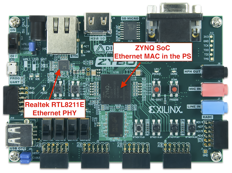
An Ethernet interface can be decomposed into two layers: the MAC and the PHY layer. These two are often implemented in separate integrated circuits (ICs), especially in the context of FPGA design. The MAC, in our case, is implemented in the ZYNQ Processing System (PS), so unlike in other FPGAs, it is hard, meaning it can not be “removed” from the chip and it does not need to be instantiated through the Programmable Logic (PL). Meanwhile, the PHY is provided by a chip that is external to the ZYNQ SoC. In the case of the ZYBO board, the PHY is implemented in the Realtek RTL8211E-VL IC, as described in the [ZyboManual]. So, to be visual, it looks as follows:
Media Independent Interface between the MAC and the PHY
Once we know where the MAC and the PHY layers are, the next step is to understand how they communicate with each other. As the diagram below shows, the communication between the MAC and PHY layers can be made through several different flavors of an interface called “Media Independent Interface” (MII). One of them is the so-called Gigabit Media Independent Interface (GMII) that is shown. Other options are, for example, the Reduced GMIII (RGMII), which requires half the number of data pins with respect to the GMII, and the Serial-GMII, which requires even less, only 4 differential outputs: Tx data, Rx data, and the two corresponding differential clocks, as described in [SGMII]. We, therefore, must first understand which interface our MAC can provide and which one the PHY chip expects.
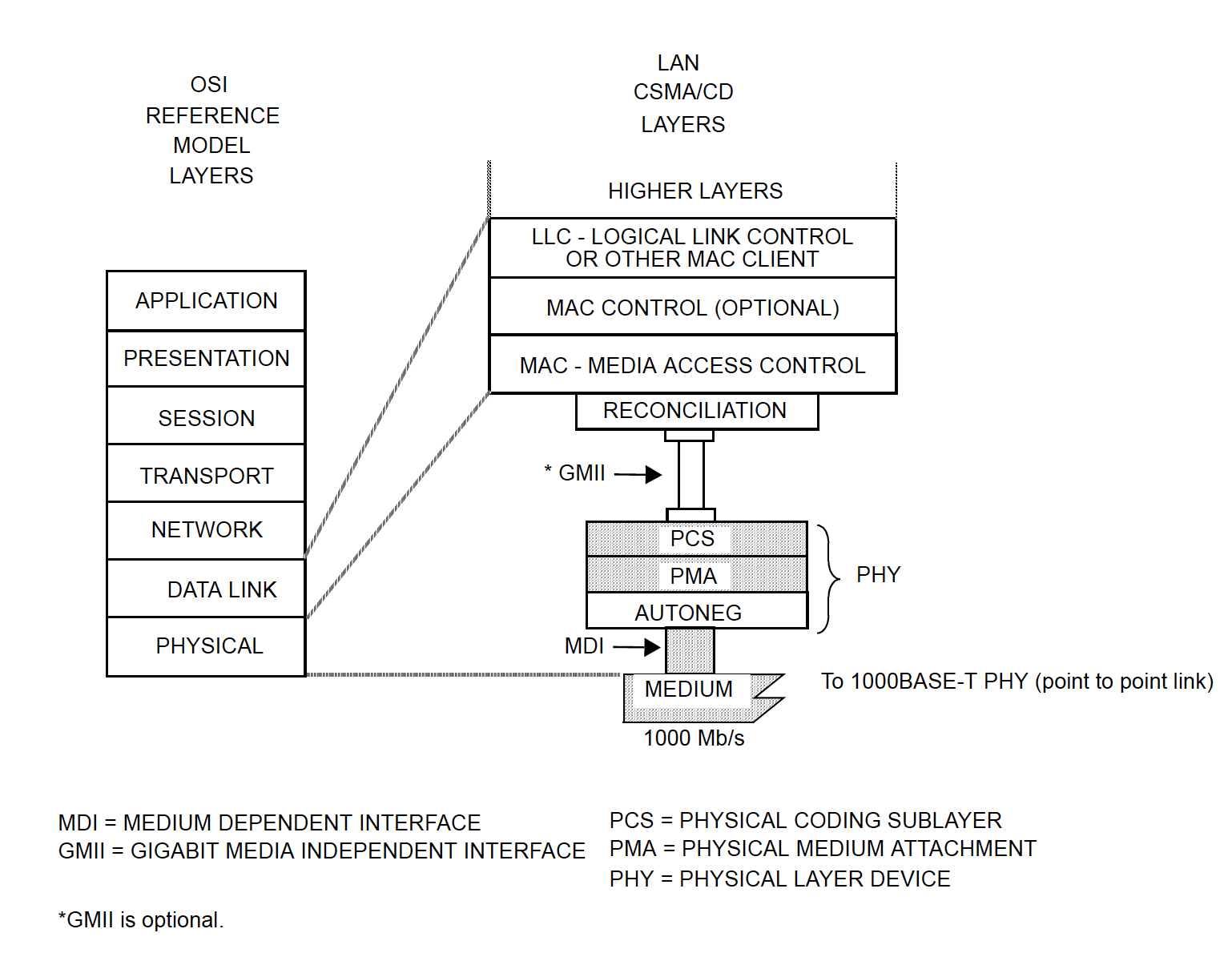
It turns out that the MAC implemented in the PS part of the ZYNQ connects through an RGMII interface that is routed across the Multiplexed Input/Output (MIO) interface of the ZYNQ PS. Additionally, it can provide a GMII interface through the EMIO (if you are not familiar with the EMIO, check the ZYNQ manual, it is when PS peripherals are routed through the PL). The difference in the interface comes from the fact that the MIO is more limited in the number of available IO pins, so it makes sense to not occupy it with the high pin count of the GMII and instead use the RGMII (reduced GMII).
The reason why a GMII interface can be provided to the PL is that some applications may need to instantiate some PHY sublayers within the PL. For example, if the goal is to implement an SGMII interface between the MAC of the ZYNQ PS and an external PHY, then we would need to implement an IP called “PCS/PMA or SGMII core” in the PL (and this would be possible only on FPGAs that have gigabit transceivers). This IP, in turn, would be configured in the SGMII bridge mode, as described in [PCS/PMA]. But don’t worry about this now, since we won’t need it.
The Realtek RTL8211E-VL PHY flexibly accepts both GMII and RGMII interfaces for 1000BASE-T operation. And by the way, if you don’t know what 1000BASE-T is, it is just a name for an Ethernet interface capable of 1 Gbps data rate and that communicates through the well-known twisted-pair copper cables. Now, since an RGMII interface is availed through the ZYNQ MIO (in the PS part of the ZYNQ), we are ready, that is, we don’t need anything in the PL to make the MAC talk to the external PHY chip. The RGMII interface in the MIO already suffices.
MDIO Interface
At this point, we know where the MAC and PHY layers are implemented and how they are going to communicate with each other. However, there is still one missing interface, the one through which the MAC sends and reads configurations to and from the PHY. This interface is called the Management Data Input/Output (MDIO) interface and is accompanied by the Management Data Clock (MDC). It merely consists of two extra pins (one for each) that we need to connect to the PHY. The PS provides these outputs from the MIO too, and they are routed to appropriate pins (connected to the PHY) in the ZYBO board. So, yes, we are ready!
Sending and Receiving Data through ZYNQ Ethernet
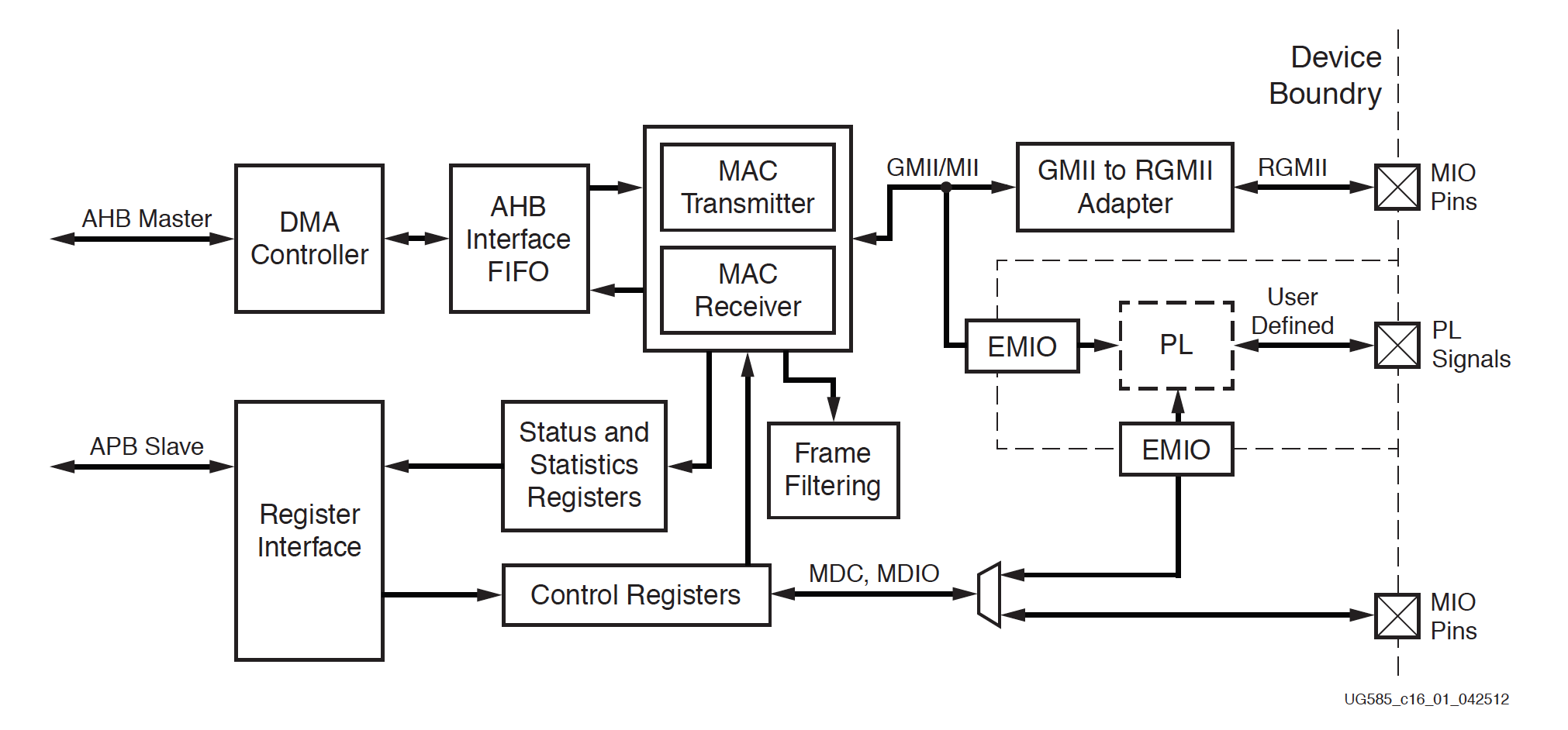
In summary, the previous section explained that we use the hard MAC of the ZYNQ SoC, connect it to the external PHY through the RGMII interface of the MIO and manage the configuration of this PHY chip through the MDIO. Now, the question is, how are we going to send a receive data through this Ethernet interface? As explained in the [ZynqManual], the MAC Transmitter and Receiver modules (in the PS) are connected to a FIFO, which, in turn, exchanges data with memory through a DMA controller. When transmitting, data is first fetched from memory and written into this FIFO, then the FIFO passes this data on to the MAC Tx chain. In the opposite direction, the MAC Rx writes the received data into the FIFO, and the DMA sends this data to memory. This is depicted below in the diagram of the Ethernet controller.
The operation of the DMA is detailed in a dedicated post. For now, we can advance into the hardware design and concentrate on the Ethernet configuration.
Hardware Design in the ZYBO board
The following steps create a simple hardware design that is sufficient for experimenting with the Ethernet interface in the ZYBO board.
- Create a new project.
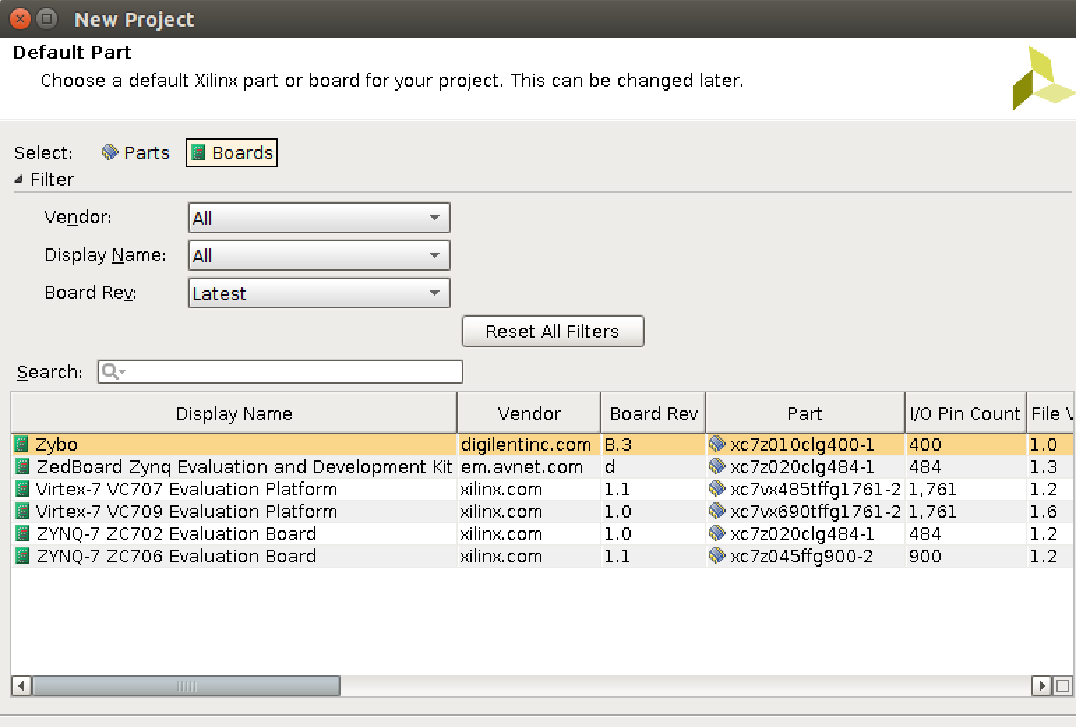
- In the “Default Part” dialog, set the Zybo board, as shown below. If the Zybo is not listed, make sure you include the Zybo board configuration file. It is not straightforward to find this file, but you can find it in one of the Zybo tutorials at the Xilinx University Program (XUP).
- Create a block design.
- Add the ZYNQ Processing System IP.
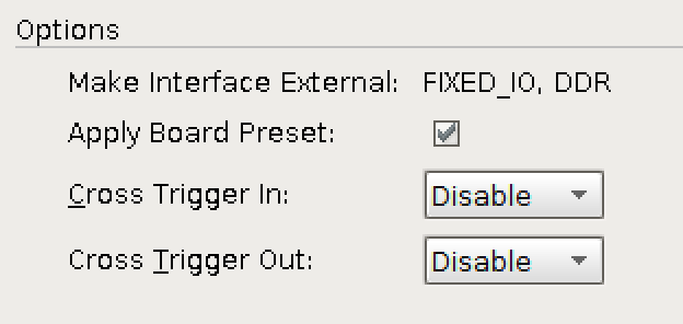
- Run block automation and apply the board preset, as follows:
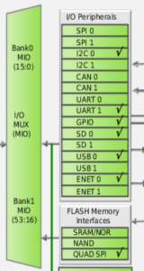
- Note that one of the two Gigabit Ethernet controllers is enabled in this configuration (ENET 0):
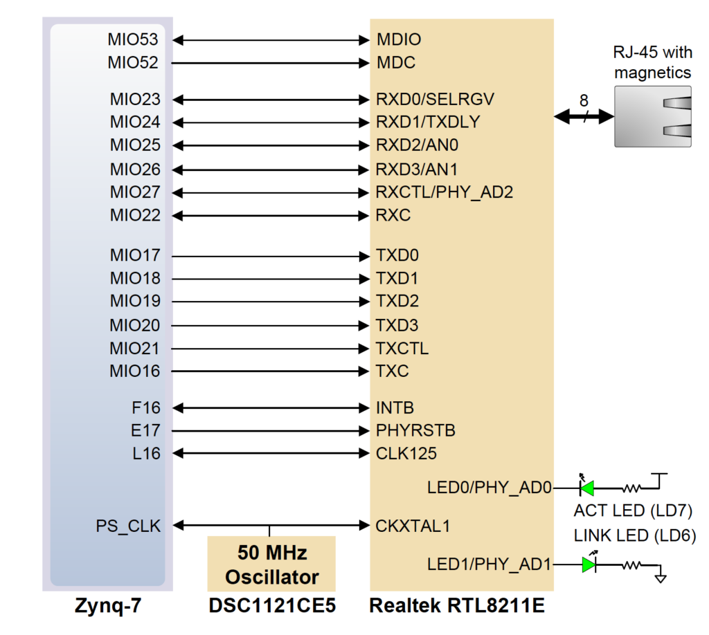
- Note that the RGMII interface, MDIO and MDC pins are routed through the ZYNQ MIO towards the External PHY, as seen below.
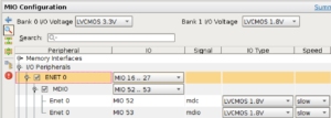
More specifically, note that the RGMII interface occupies MIO pins 16 to 27, while the MDIO and MDC pins are mapped to MIO pins 52 and 53, and that these assignments comply with the routing in the ZYBO board, as depicted in the following diagram:
- Go to the PS-PL configuration pane. Expand “AXI Non Secure Enablement -> GP Master AXI Interface” and disable the AXI master interface 0, which we will not use (and was added through the preset configuration).
- Save the design.
- Validate the design.
- Create an HDL wrapper.
- Generate bitstream.
- (File -> Export -> Export Hardware). In case you don’t know, include the bitstream only in case you prefer to program via the SDK. I normally prefer to program through the Vivado Hardware Manager, so I leave this option unselected.
- Launch the SDK.
- With the SDK open, create a Board Support Package (File -> New -> Board Support Package). The default configuration is okay.
- After creating the BSP, the system.mss file will be opened. Then, go to its “Peripheral Drivers” section and find ps7_ethernet_0. Then import the “intr_dma” example.
Software
Now, the remaining part is to understand the “intr_dma” example application and use it to test the system. In the sequel, an overview of the application is provided, with focus on the Ethernet configuration.
Initialization
Conventionally, Xilinx drivers for Ethernet MAC (EMAC) IPs normally start with functions like the XEmacPs_LookupConfig and XEmacPs_CfgInitialize. The first essentially reads information of the hardware defined in the Vivado project from the xparameters.h file (exported to the SDK project) and returns this information in an organized structure. In the current case, the most important information is the address to which the EMAC is mapped on memory. After this information is obtained, the second function (XEmacPs_CfgInitialize) initializes a structure of type XEmacPs that contains the EMAC configurations, with all default values and including the particular address obtained from the first function (XEmacPs_LookupConfig). This structure will, then, be used whenever a configuration is to be written to the EMAC.
Ethernet Tx Clock
The next thing that the example application does is to configure the Ethernet Tx clock through the so-called System-Level Control Registers (SLCRs). This is done by configuring the GEM0_CLK_CTRL register such that a 125 MHz clock is provided to the MII, where data is transferred at 8-bit per cycle (125 * 8 gives 1Gbps, as required). And to do so, first the SLCRs have to be unlocked by writing to the ZYNQ register called SLCR_UNLOCK, then, after configuring the two registers, the SLCRs must be locked back. This is a standard procedure every time one of the SCLR registers needs to be configured.
Ethernet MAC Address
Next, the MAC address of the device is set by:
Status = XEmacPs_SetMacAddress(EmacPsInstancePtr, EmacPsMAC, 1);
It defaults to “{0x00, 0x0a, 0x35, 0x01, 0x02, 0x03}”. Pay attention to this address, as it will be useful when debugging frames transmitted by the FPGA on a computer (i.e. on Wireshark). And by the way, note that “0x00, 0x0a, 0x35” (the upper 24 bits of the address) corresponds to the Xilinx organizationally unique identifier (OUI), so if you use Wireshark, you can notice that it interprets the address as pertaining to a Xilinx device and labels the incoming frames like this:

PHY Configuration
Now let’s advance to the most important part of this tutorial, the configuration of the PHY. The following steps will be essential to make the Ethernet interface functional in the ZYBO board.
MDC Clock
As noted earlier, the external PHY transmits and receives data through the RGMII interface, but it is configured through the dedicated and standardized MDIO interface. This MDIO interface, in turn, is clocked by a clock signal called MDC that must be fed to the PHY by the MAC. Hence, the first thing to do is to generate the appropriate MDC clock (with the appropriate frequency not exceeding 2.5 MHz). Since the MDC is generated by dividing the CPU_1X clock of the ZYNQ PS, it is only necessary to configure the divisor. This is done by the following function call:
XEmacPs_SetMdioDivisor(EmacPsInstancePtr, MDC_DIV_224);
sleep(1);
MDIO Registers
The subsequent lines put the PHY in loopback mode (so that frames are not sent over the twisted-pair line), reset the PHY and configure the speed to 1Gbps.
EmacPsUtilEnterLoopback(EmacPsInstancePtr, EMACPS_LOOPBACK_SPEED_1G);
XEmacPs_SetOperatingSpeed(EmacPsInstancePtr, EMACPS_LOOPBACK_SPEED_1G);
However, for the purpose of this tutorial, we do not want a loopback. Instead, we want to check that the frames are effectively sent over the Ethernet cable, by inspecting them in the link partner (in my case the computer). Hence, the loopback mode will be disabled.
To disable the loopback mode and for other things soon to be explained, the next steps consist in interactions with the so-called MDIO registers, so it is worthwhile to present some background. As explained before, the MDIO is a serial bus that allows the MAC to manage the PHY. In particular, it does so by allowing the MAC to read and write to (from) a set of management and status registers in the PHY, among which there are both standard registers and vendor-specific registers.
Every time the MAC needs to configure or read a configuration or status from the PHY, it must do so by the MDIO bus. In the application, this is done by the following functions:
XEmacPs_PhyRead(XEmacPs *InstancePtr, u32 PhyAddress, u32 RegisterNum, u16 *PhyDataPtr)
XEmacPs_PhyWrite(XEmacPs *InstancePtr, u32 PhyAddress, u32 RegisterNum, u16 PhyData)
where PhyAddress is the address corresponding to the PHY that is targeted (there could be multiple PHYs, e.g. in a switch), RegisterNum is the number of the target MDIO register to be read or written and PhyData holds the read value or the value to be written.
Disabling Loopback Mode
That said, let’s proceed to the actual configuration. First, the loopback mode will be disabled. To do so, enter the EmacPsUtilEnterLoopback function and find the following line:
PhyReg0 |= PHY_REG0_LOOPBACK;
This line sets the loopback mode in the Register 0 of the MDIO register-space. This register is standardized by IEEE 802.3, so all Ethernet PHYs enable/disable the loopback mode in the same bit of register 0. Instead of enabling loopback, change this to:
PhyReg0 &= ~PHY_REG0_LOOPBACK;
This ensures that the loopback bit is cleared (disabled). Hence, once this configuration is written to the external PHY through the MDIO interface, by
Status = XEmacPs_PhyWrite(EmacPsInstancePtr, PhyAddr, 0, PhyReg0);
loopback will be disabled.
PHY-specific MDIO Registers
Next, look for the following block of code (which is actually before the line that enables loopback):
/*
* Switching to PAGE2
*/
PhyReg22 = 0x2;
Status = XEmacPs_PhyWrite(EmacPsInstancePtr, PhyAddr, 22, PhyReg22);

/*
* Adding Tx and Rx delay. Configuring loopback speed.
*/
Status = XEmacPs_PhyWrite(EmacPsInstancePtr, PhyAddr, 21, PhyReg21);
/*
* Make sure new configuration is in effect
*/
Status = XEmacPs_PhyRead(EmacPsInstancePtr, PhyAddr, 21, &PhyReg21);
if (Status != XST_SUCCESS) {
EmacPsUtilErrorTrap("Error setting Reg 21 in Page 2");
return XST_FAILURE;
}
/*
* Switching to PAGE0
*/
PhyReg22 = 0x0;
Status = XEmacPs_PhyWrite(EmacPsInstancePtr, PhyAddr, 22, PhyReg22);
You can remove all of these lines, because they are not valid for the specific PHY that we are using. If interested, you could verify that by looking into the Realtek RTL8211 datasheet and searching for the above registers. You would see that they do not exist. Apparently, the example application was developed for a Marvell PHY (probably the 88E1116R of the ZC706 board).
Auto-negotiation
Finally, we have to properly handle the PHY auto-negotiation. The latter is a standardized handshaking carried by the external PHY with respect to the link partner, through which it discovers the capabilities of the partner and negotiates how to communicate over the link (in terms of speed and duplexing mode). During this process, the external PHY will advertise its capabilities (written in MDIO register 4) and store the link partner’s capabilities (in MDIO register 5). Once this auto-negotiation is concluded, the external PHY will flag this status in MDIO register 1. Then, the application can proceed normally and the Ethernet frames will effectively be transmitted as desired. In fact, this requirement of waiting for the completion of the auto-negotiation during PHY initialization is explained in section 16.3.4 of the [ZynqManual]
In the application, what is necessary is to poll the auto-negotiation complete status bit in MDIO Register 1 of the external PHY. This can be done by adding the following lines after the lines that write the loopback mode configuration (now written as “disabled”) :
Status = XEmacPs_PhyRead(EmacPsInstancePtr, PhyAddr, 1, &PhyReg1); while (!(PhyReg1 &PHY_R1_AN_COMPLETE)) { XEmacPs_PhyRead(EmacPsInstancePtr, PhyAddr, 1, &PhyReg1); sleep(1); } xil_printf("Auto-negotiation Complete\r\n");
where the constant must be defined as:
#define PHY_R1_AN_COMPLETE 0x0020
and a declaration of u16 PhyReg1 must obviously be added before the function.
Once the wait is completed, the application could read the content of MDIO Register 5 to obtain the negotiated configuration and properly configure its local PHY. Nevertheless, here it suffices to only wait for the completion. Besides, it should be noted that if the above does not work (the auto-negotiation never completes), it is probably because the auto-negotiation is not enabled. Make sure you enable it within the Register 0 (bit 12).
Moreover, it is also useful to wait until the link status indicator of MDIO Register 1 indicates that the link is up. This can be done by adding the following code:
while (!(PhyReg1 & PHY_R1_LINK_UP)) {
    XEmacPs_PhyRead(EmacPsInstancePtr, PhyAddr, 1, &PhyReg1);
    for(i=0; i < 0xfffff; i++);
        sleep(1);
}
xil_printf("Link is Up\r\n");
which uses the constant:
#define PHY_R1_LINK_UP 0x0004
That concludes the configuration. Now you are ready to test.
Testing
To test the application, simply plug an Ethernet cable between your computer and the ZYBO board. Launch Wireshark, start a capture in the Ethernet interface card that was connected to the ZYBO board and run the application in the SDK. Wireshark is expected to receive the frame transmitted by the Zybo board.
That concludes the tutorial. Please, feel free to leave comments or questions.
References
[ZyboManual] ZYBO Reference Manual. February 14, 2014
[ZynqManual] Zynq-7000 All Programmable SoC – Technical Reference Manual. UG585 (v1.11) September 27, 2016.
[SGMII] Chu, Y. C. (2001). Serial-GMII specification. Revision, 1, 3.
[PCS/PMA] pg047 – 1G/2.5G Ethernet PCS/PMA or SGMII v15.0
Leave a Reply